Project Description
Client: Los Angeles Chargers
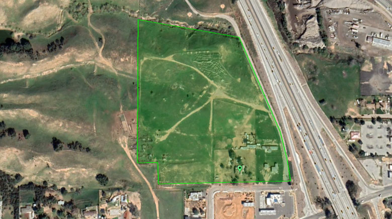
Location: El Segundo, California
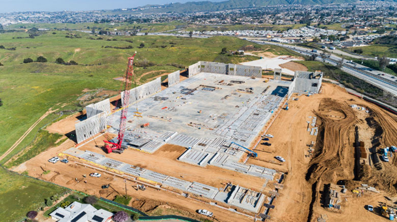
Our scope of work included investigation of the site and preparing a comprehensive design report, review of construction plans, interactions with the design team, and quality control services during construction of the project.
The Challenges
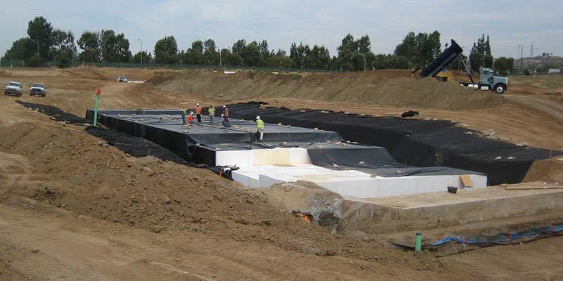
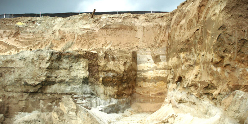
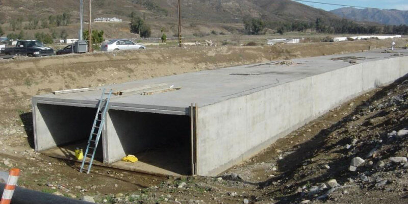
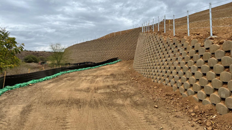
Specific geotechnical challenges included using lightweight geofoam blocks for backfilling a large retaining wall to avoid surcharging an existing RCP storm drain pipe, 108 inches in diameter. Several other existing utilities required protection in place. The project also entailed a design that did not impact the existing foundations of the MTA Elevated rail line bridge and provided a stable, well-drained surface to support the practice fields.
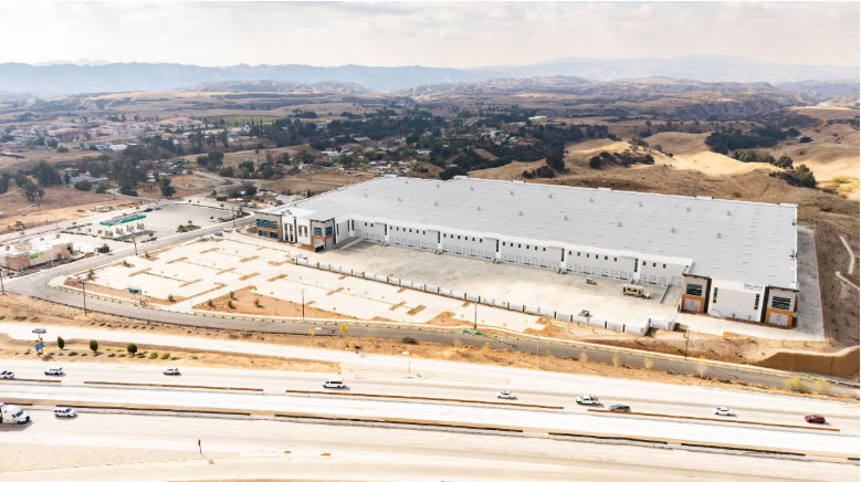
Project Highlights
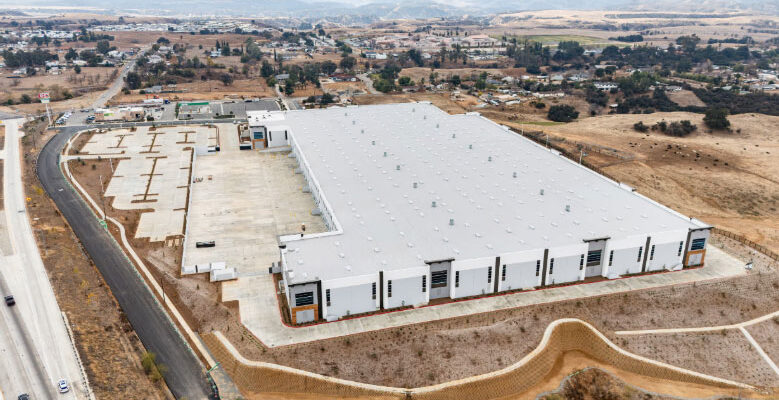
3-story building, 142,500 square feet in size
Three Natural grass practice fields
1,600 square foot elevated outdoor terrace
3,400 square foot elevated outdoor turf area
Two-lane lap pool
3,100 square foot media Center
Rooftop hospitality club
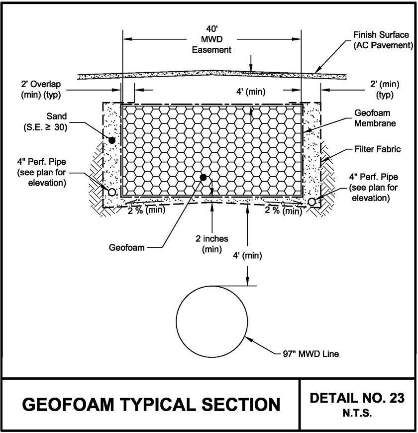
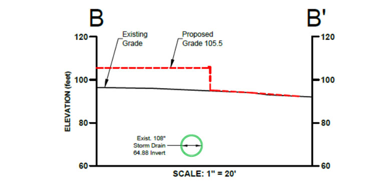
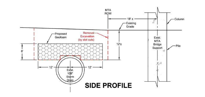
Proposed site development called for raising the grade by up to 12 feet above the existing 108” RCP. Review of old construction plans indicated the pipe was not designed to support such high loads. To mitigate surcharging, soils above the pipe were removed. Geofoam blocks having a total thickness of 6 feet were placed over the pipe and beyond. The reduction in soil weight allowed for the addition of fill soil over the original grade without overloading the pipe.
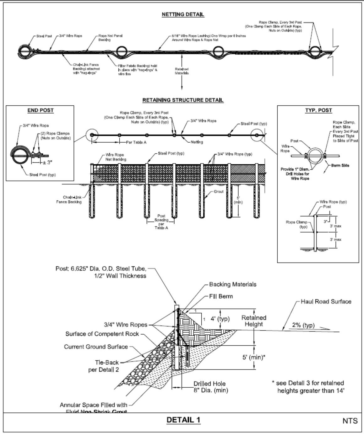
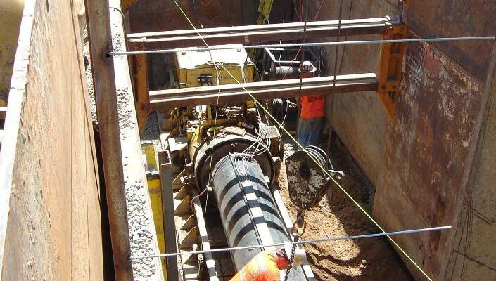
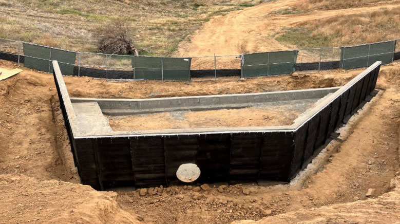
A second 54-inch storm drain pipe was to be protected in place. New site development would place the pipeline near the surface and below future paving areas.
-

- Section showing existing and proposed configuration
-
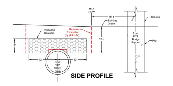
- Section showing temporary excavation and placement of Geofoam. (Not To Scale)
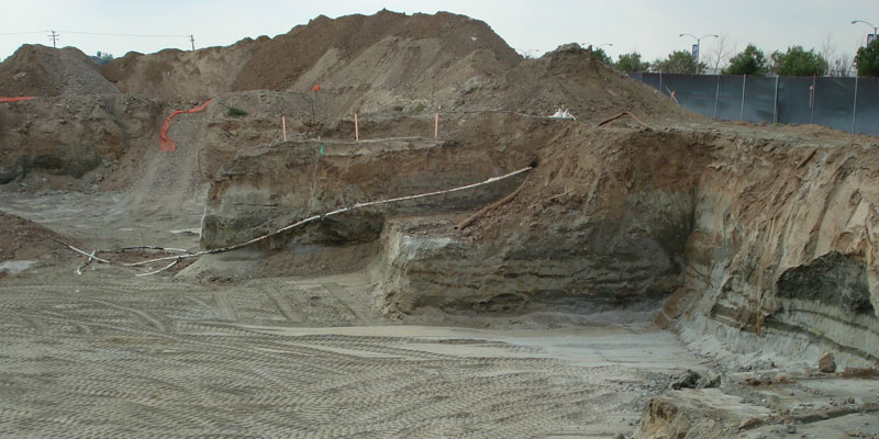
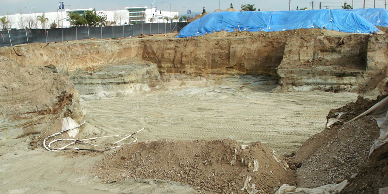
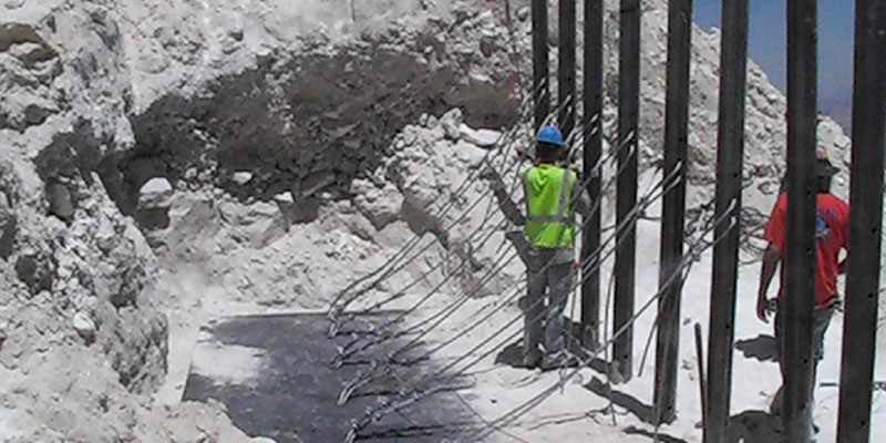
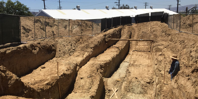
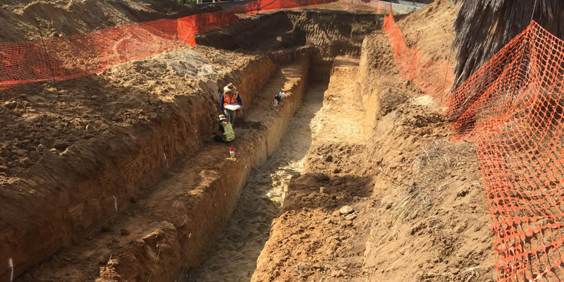
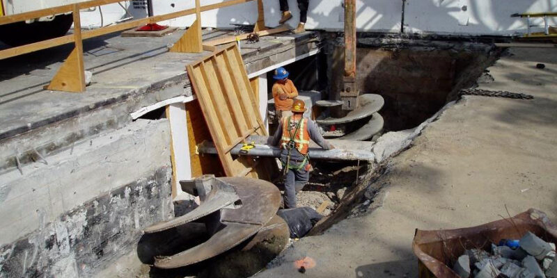
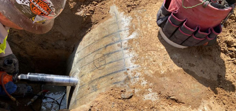
As part of the evaluation of the existing storm drain pipe, a pit was excavated to expose part of the pipe. Geophysical equipment was used to identify the locations of reinforcement. Cores were then taken from the pipe to provide specimens for compression testing and to identify the sizes of reinforcing bars. With this data, analyses were performed by our firm to evaluate the loading capacity of the pipe and confirm that future traffic would not over-stress the pipe.