


Project Description
Client: West Basin Municipal Water District (WBMWD)
Location: El Segundo, California
Project: 42-inch Water Line
Ground subsidence of up to 2 feet was observed following the backfill of a 60-inch RCP storm drain pipe that crossed 35 feet under an existing and active 42-inch reclaimed water line for West Basin Municipal Water District (WBMWD) in El Segundo, California. The likely causes were attributed to consolidation of loose storm drain trench backfill and consolidation of native soil disturbed by the installation and removal of sheet piling that had been used along the sides of the storm drain trench during construction.
The Challenges
The storm drain was constructed for the Plaza Del Segundo commercial/retail development by Comstock Crosser & Associates. This firm was contracted by the developer to come up with a plan to mitigate future settlement and resulting damage to the reclaimed water line (RWL). Considering the sand nature of the onsite soil, we proposed that the loose soil supporting the water line be treated with a chemical grout to provide some compaction and to cement the soil, giving it strength to support the RWL, and to treat the remaining loose soil by removals to near the top of the storm drain pipe and water jetting along the sides to consolidate the sand shading. Following the water jetting, the backfill could be replaced with the soil removed, placed in lifts compacted to the specified relative compaction values. These proposed measures were adopted, and we were contracted to develop and oversee the mitigation measures.
This firm developed the construction plans and technical provisions for the work, which included setting up settlement monitoring devices prior to construction, laying out chemical grout injection points and injection sequencing, performing Cone Penetrometer Testing (CPT) within the treatment zone following completion of grouting, providing a sand/cement slurry cradle along and under the RWL, and construction methods for mitigating the loose storm drain backfill.
Prior to the work, we set up 6 settlement plate monitors placed directly on the 42-inch pipe and installed Sondex settlement monitoring devices within the grout treatment zone at 4 locations to monitor settlement during chemical grout operations. Reading of these devices was taken multiple times a day during grouting operations. Minor measurable changes were observed during the initial grouting work resulting in an adjustment of time and distance between injection points to allow curing and hardening of the grout-infused soil.
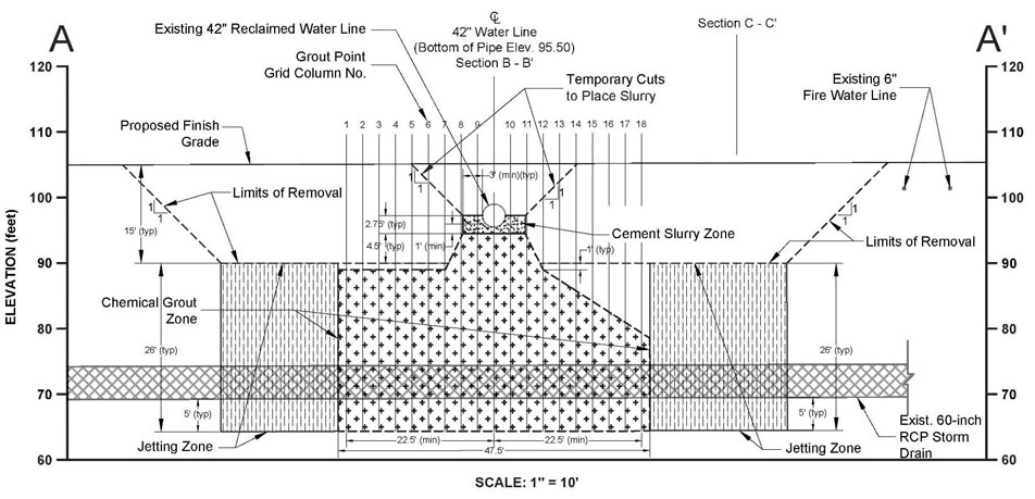
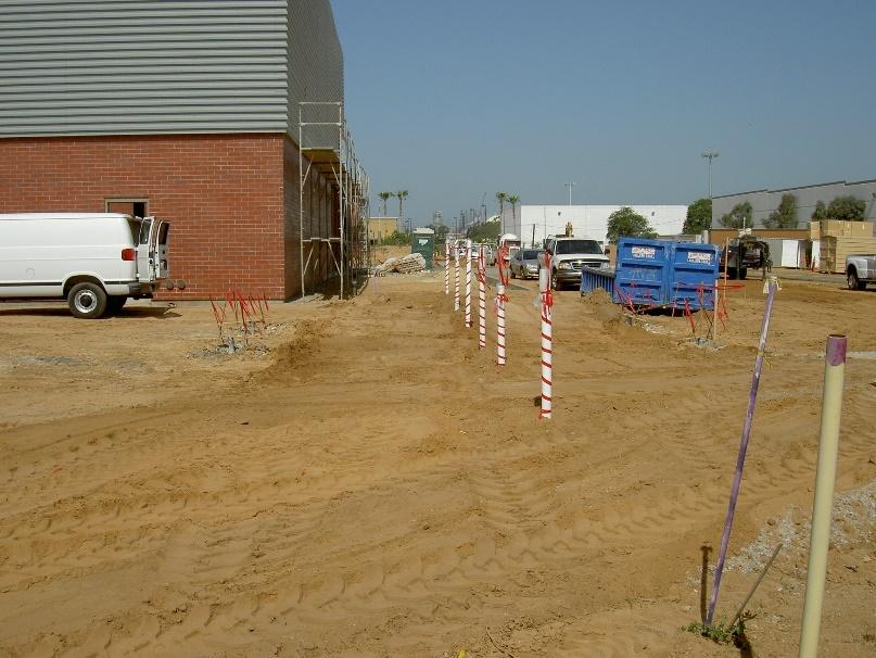
164 injection points were used to inject grout to varying depths and treatment intervals. The treatment zone was centered on the 42-inch RWL and extended about 24 feet on either side, and from 10 to 15 beyond the centerline of the 60-inch RCP storm drain. The injection points were typically spaced at 2.5-feet center to center.
The injection work was performed by Pressure Grout Company of Long Beach, CA. They provided the drill rig that drilled the injection points, the injection casing, the grout mixing equipment and supplies, and the injection pumping equipment.
Grouting was done in two phases. In the first phase, 5 of the outermost grout rows on both sides of the centerline of the RWL were grouted, and the effects of wetting the underlying soil resulting in collapse were determined through settlement monitor readings. Readings indicated some settlement, and the sequencing of installing casings and injecting were modified to allow more time, at least 5 days for adjacent points, for materials to set before installing and injecting adjacent points.
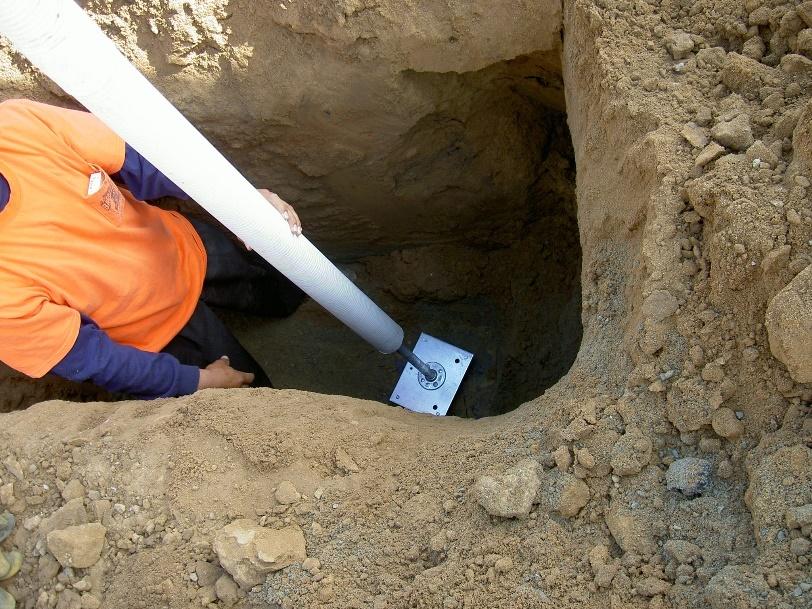
Grout was injected through a 1-inch diameter PVC pipe, capped at the bottom and with pre-drilled injection holes at 15-inch stages. The injection hose nozzle (packer) had gaskets to seal within the injection hole stages. Injections began at the bottoms and advanced upward in 15-inch increments, injecting a pre-determined quantity of grout, or until injection pressures indicated that the surrounding soil was already well compacted and did not require additional grout.
Chemical grouting operations were completed in about 30 calendar days. A total of 36,449 gallons of chemical grout was placed within the treatment zone.
Five days after the completion of grouting, Cone Penetrometer Testing (CPT) was performed by Fugro, under our direction and observation, at 6 locations to evaluate the effectiveness of the grout treatment. Project specifications called for the treated material to exhibit an unconfined compressive strength of at least 10 psi or 0.72 tons/sqft. From analyzing the CPT data, we concluded that the treatment met or exceeded the 10 psi target strength.
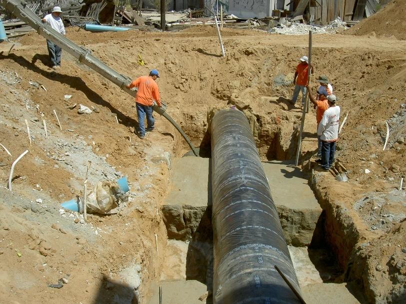
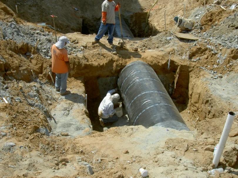
Following the chemical grout treatment, excavations were made to expose a 36-foot-long section of the 42-inch RWL, centered over the underlying 60-inch storm drain pipe. Excavations were then made to expose the sides and bottom of the RWL. To provide continuous support of the RWL, excavations were made in four alternating sections, each approximately 9 feet in length, to at least 3 feet lateral clearance from the pipe edges, and below the pipe to expose soil treated with chemical grout (but not less than 1 foot). A spray of water and phenolphthalein was used to identify that treated soil was exposed, with the spray turning magenta in color when it reacted with the cement in the grout.
A representative of WBMWD was present when sections of the pipe were exposed to inspect the condition of the pipe. No damage to the pipe was noted except for some tears in the plastic membrane covering the pipe. At the direction and observation of the WBMWD’s representative, new plastic membrane was installed over the damaged sections.
Following the inspection of the pipe and repairs to the membrane, the excavations were filled to at least mid-pipe with a 2-sack slurry. Slurry for sections 1 and 3 were allowed to set for 2 days before excavating for sections 2 and 4.
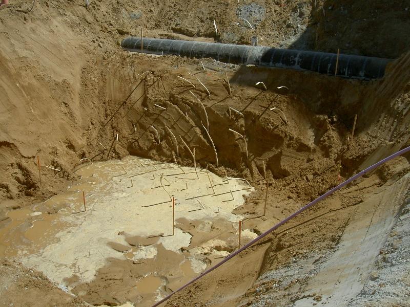
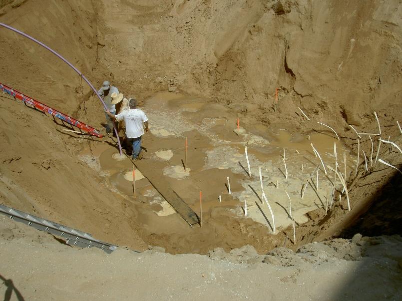
After the RWL was sufficiently supported, excavations were made to remove and treat the backfill and edges of the 60-inch storm drain trench excavation. 15 feet of the trench backfill was removed on either side of the RW to expose the soil backfill to be jetted. Excavations along the RWL stopped at the exposed the chemical grout treated soil (note the white 1-inch PVC injection casings in the photos below).
The remaining 26 feet of storm drain backfill was treated to consolidate the sandy soil with water jetting, from the bottom up. A 20-foot long, 1.5” PVC pipe was used, attached by a 2” fire hose connected to a fire hydrant. With water flowing through the pipe, it was pushed into the jet zone to depths of 22.5 to 25 feet, held until water returned to the surface or settlement of surficial material was observed. The pipe was then pulled up in approximately 5-foot intervals and the jetting repeated. Jet points were spaced 2.5-foot center to center. Onsite sands at the removal surface were flushed into holes left by the jetting pipe until holes were filled. Material exposed at the surface within the jet zones were observed to settle from 0.5 to 0.75 feet during jetting.
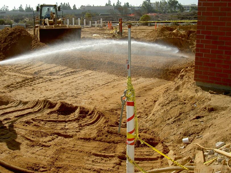
The materials removed to expose the jetting zone surface were used to backfill those excavations. The backfill was placed in 6- to 8-inch loose lifts that were moisture conditioned to near the optimum moisture content, and then compacted by wheel-rolling using a large rubber-tire loader. At the direction of the WBMWD onsite representative, lighter, manually operated compaction equipment was used to compact the backfill directly over the 42-inch RWL until at least 5 feet of backfill over the pipe had been placed.
This firm provided observation and field density testing of the backfill operations to verify that work was performed in substantial conformance with the project specifications and technical provisions, the grading codes of the City of El Segundo, and applicable portions of the project geotechnical requirements.
Based on our observation during work and the results of CPT testing, the chemical grout treatment of soil materials supporting the 42-inch reclaimed water line and placement of slurry were considered suitable to mitigate the potential for future settlement of the pipe.
Also, based on our observations and field density testing, the removal of loose storm drain materials, water jetting of soils loosened by previous sheet-piling, and compacted backfill replacement was considered suitable to prevent settlement of overlying surface improvements.
Comstock Crosser & Associates was very pleased that the problem was repaired in-place, as opposed to major removal and replacement operations. West Basin Municipal Water District was equally pleased that their waterline was protected and sufficiently supported and that mitigation work was performed without damage or undo risk to the integrity of the 42-inch reclaimed water line.